Visual & Interactive Computing;
Introduction
(Skip Technical Section)Visual and Interactive Computing (VIC) was all about OpenGL and C++. Specifically OpenGL version 1.2 which was from the 1990's and in one form or another responsible for the Computer Generated Images of the time such as Star Trek the Next Generation and Terminator II.
Note that OpenGL was actually designed for the language C though for simplicity's sake and due to C++ being wholy compatible with C and that this unit was about C++ I will refer only to C++ from here on.
But what is OpenGL from a basic level? It is a graphics library that one could access through the Programming Language C++ and on the same note though from a more technical perspective it was a variety of C++ commands that could be fed into the OpenGL library that would in turn access the Graphics Processing Unit (GPU) or perhaps the underlying Graphics subsystem of the Computer (in Windows case the GDI) or perhaps even perform a series of mathematical functions on a two dimensional XY grid of Red, Green and Blue values and produce a two dimensional image that would act as a frame and in the case of real time video output (video, moving images on screen), ideally, it would produce these images 30 to 60 times a second.
jump backMarked Tutorial 1
An excerpt from the Assignment Documentation;
"In a previous tutorial, we rendered a car transmission using just a unit cylinder scaled, rotated and translated, along with pushing and popping of matrices. In this tutorial you must render a spacecraft (inspiration can come from real craft or science fiction) in a similar way. That is, by using a few suitable primitive routines (e.g. the ones I provide, but you can add 1 or two more)."
"You may of course code as many drawing functions as you need in terms of these ones, using the glRotate, glTranslate, glScale, glPushMatrix and glPopMatrix commands. "
So it was time to get to it and to make some sort of spacestation using the gl* C++ commands but firstly a short overview of what these commands do;
glRotate(202,1,0,0); //Rotate by 202 degrees on the X axis
glScale(1,2,1); //Scale (stretch the world) on the Y axis by double
glTranslate(0,0,16); //Translate origin (proceed/move) 16 units on the (current) Z axis determined by previous calls to Rotate and Scale
glPushMatrix(); and glPopMatrix();
The point of the aforementioned functions (rotate, translate and scale) is to move your position and set the skew of the XYZ world you are effectively in. The purpose of this is that when you draw a 1x1x1 cylinder (typical draw call) it will be drawn as a infinitely long pipe (if you omit the disks at the end), a small cylinder that is very wide though very short (and if you have the proper glScale call loaded with a variable, loops from big to small), a perfect 1x1x1 cylinder or a cylinder that is oval in nature on whatever axis or combination of them you please. With that in mind as you change your (the origin) position in the world (which is matrix mathematics) one could imagine it would become very challenging (and eventually error prone) to reverse these movements and skews.
Say you wanted to create a ball of yarn with sewing needles in it, well the ball would be easy you just create a sphere emanating from origin as the centerpoint but the needles (as rods) would be a little more tricky. First you would have to rotate to the point looking at the (future) needle lengthwise, translate to the middle of the needle, scale (by a large number such as 20, as in 20 units long, 1 unit high and 1 unit wide) and draw a regular old 1x1x1 cylinder. Now to draw the next needle the options from here are to make your way back to origin and start again (reverse and repeat the process) or perhaps "wing it" and direct yourself to the right position and while perfectly do-able (though cumbersome) there is a more present danger of introducing errors and corrupting the mathematical matrix that holds all the values to make this entire endeavour possible, in other words as the world gets bigger the more components will start to deviate away from each other, randomly.
But lucky for us (and perhaps thankfully) there is a solution out there and that solution is ofcourse gl Push and Pop, a solution so simple it probably didnt warrant that previous introduction, and the analog to Push and Pop is Save and Load. In other words, before you rotate to point in the direction of the needle/rod, translate, scale and draw you call glPushMatrix(); and that saves your position on "the stack" (LIFO in other words) as a mathematical matrix, then you perform your rotate, translate, scale and draw for the needle and instead or reversing the procedure you simply call glPopMatrix(); and you are back to where you were ready to start again.
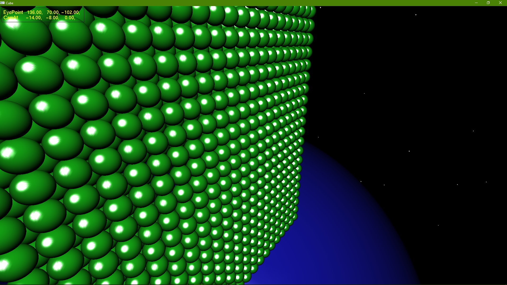
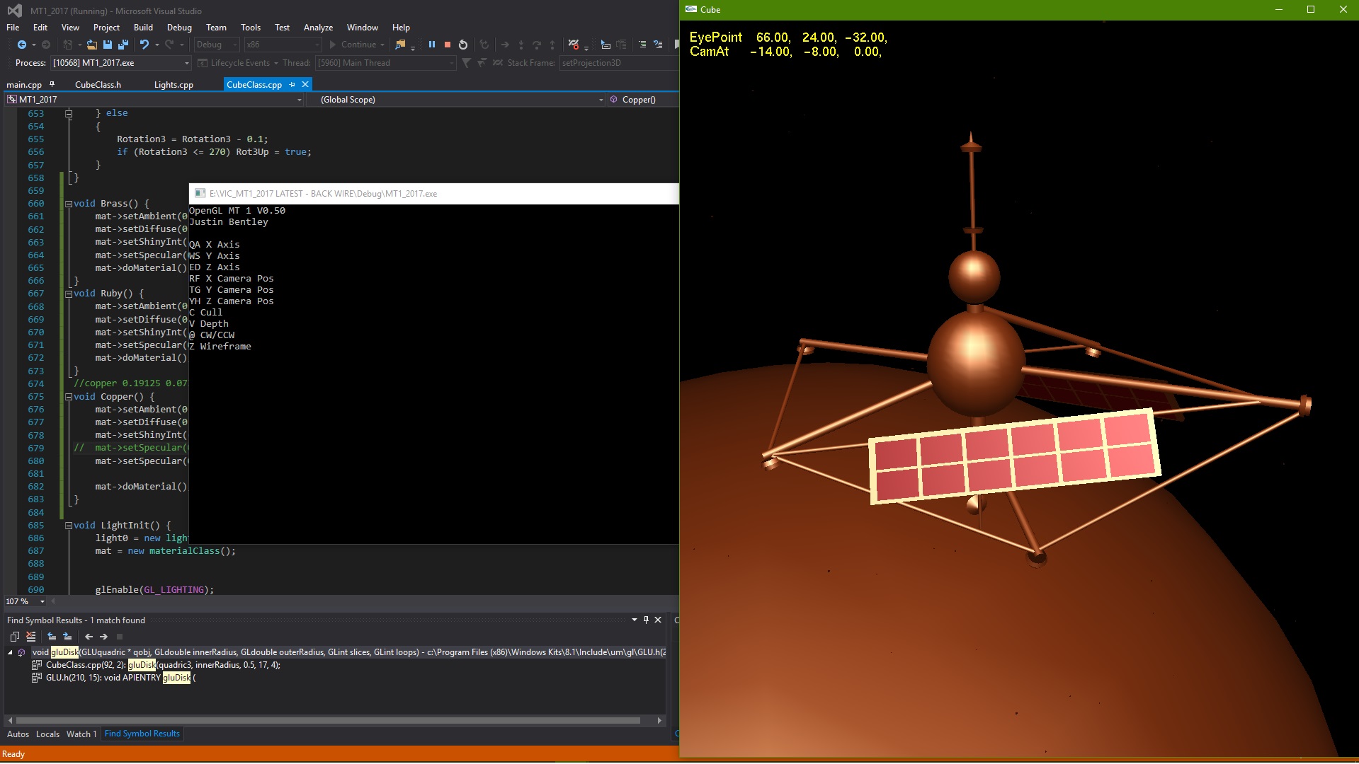
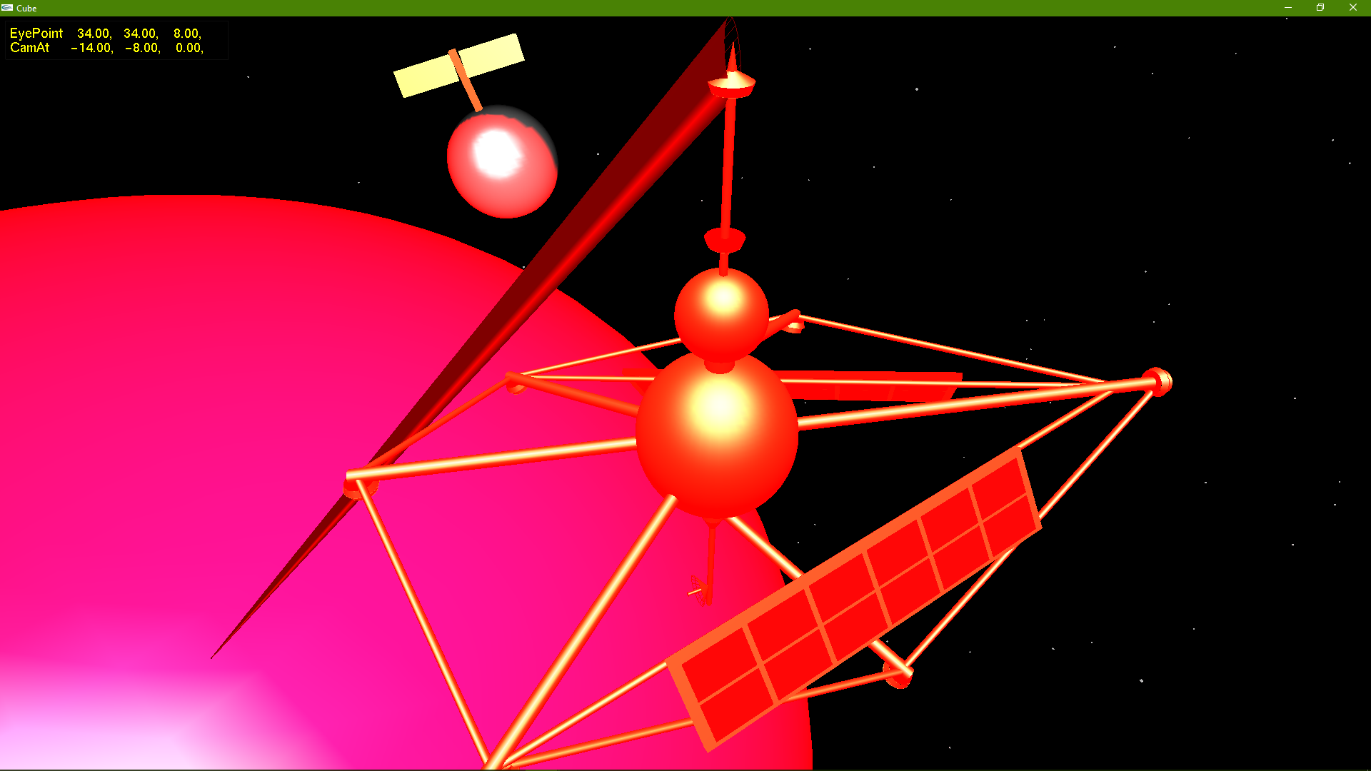
Here is a picture of OpenGL 1.2 in action;
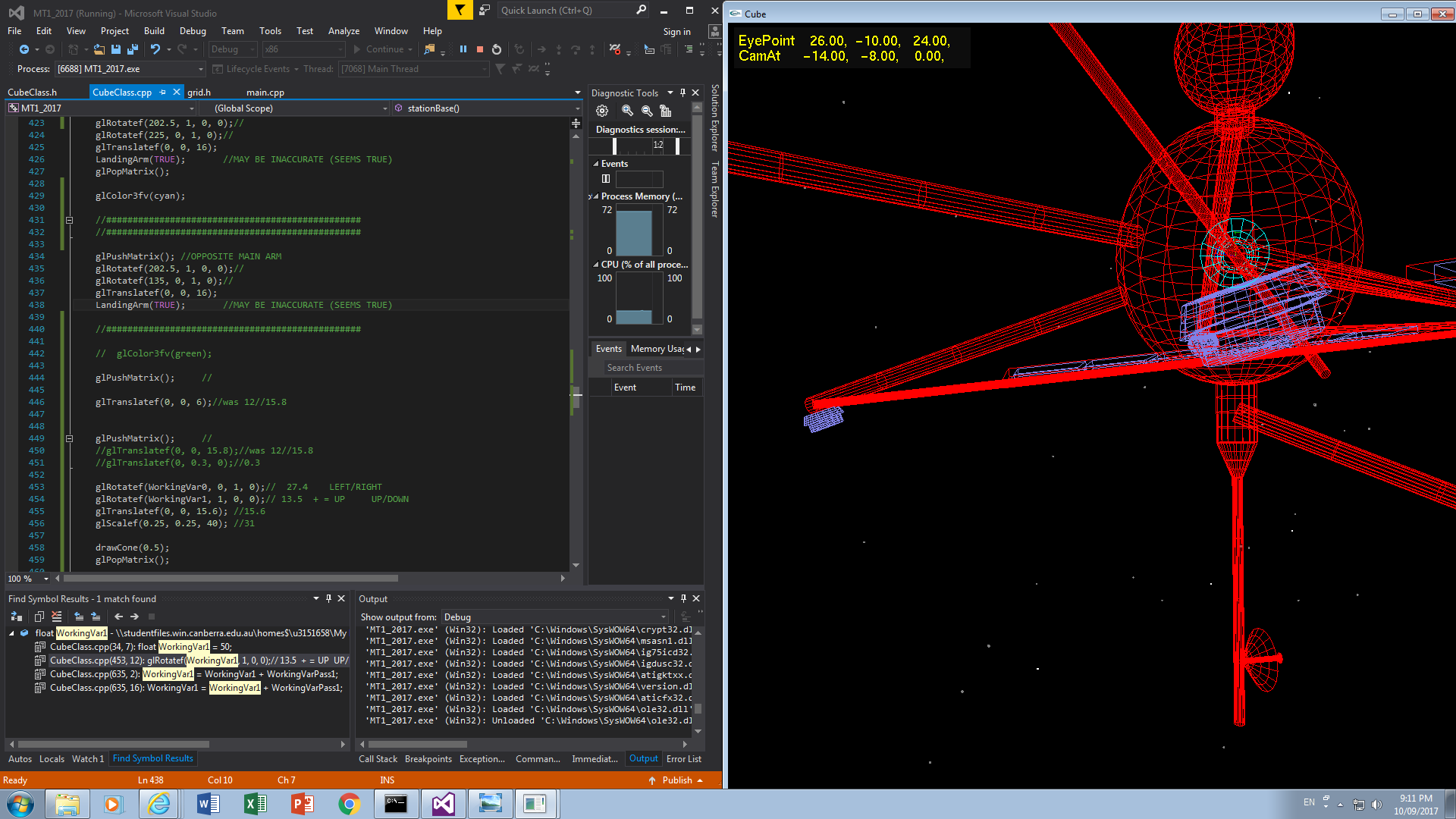
It turns out the quickest and easiest method of fine tuning your polygons is to map a variable that can be used by the keyboard, fine tune it, breakpoint it and manually enter the value;
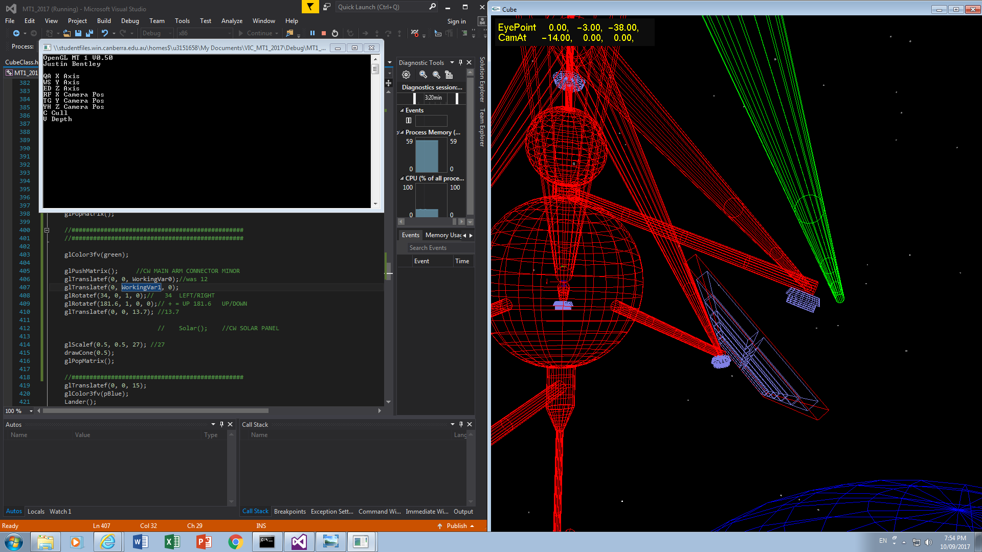
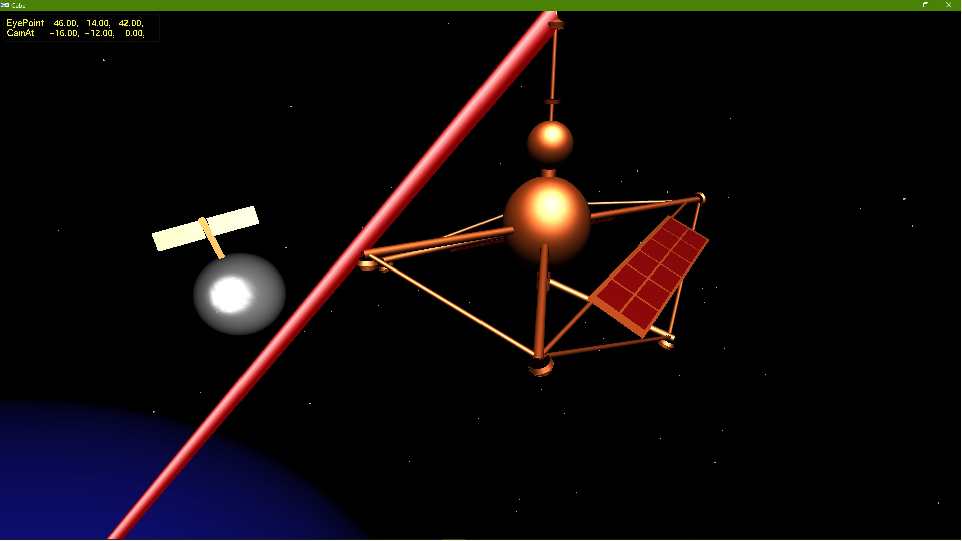
If anyone is starting to recognise the space station its from James Bond's Moonraker, the next two pictures what can be seen on the left are material values (Red, Green and Blue) for Lighting;
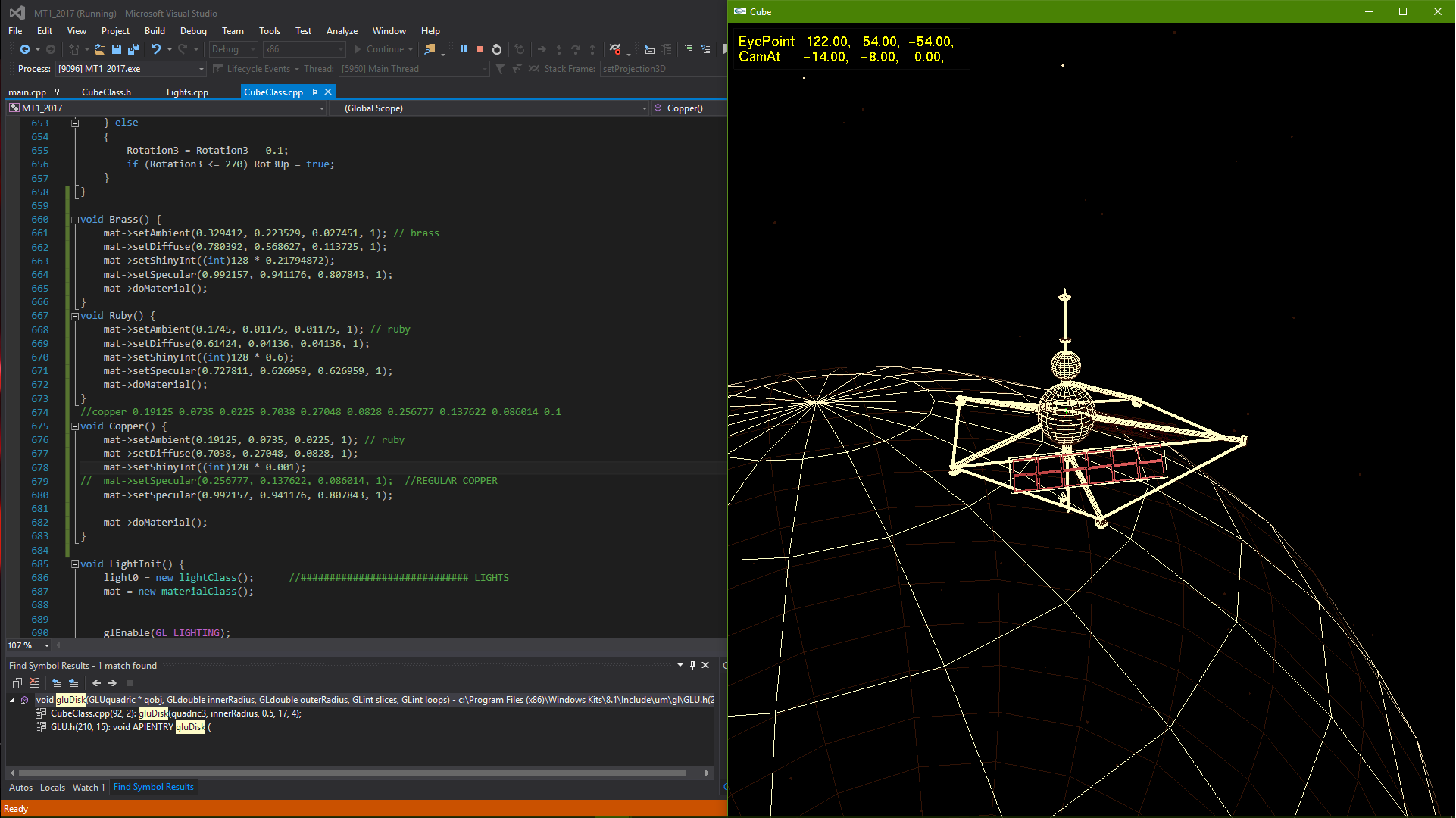
With my own small splash of The Man with the Golden Gun;
Marked Tutorial II
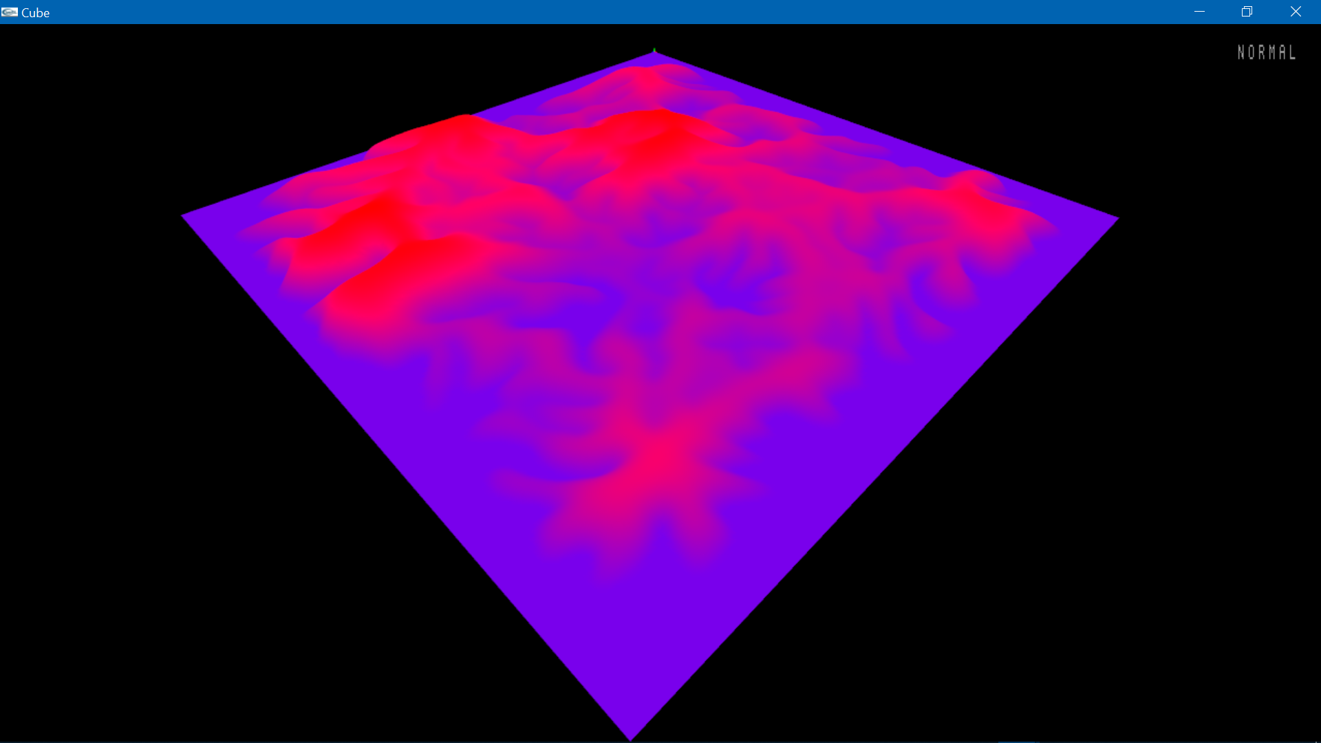
Height Fields / Digital Elevation Models

A Height Field or Digital Elevation Model (or simply DEM) rendered with lighting and materials in wireframe (the label lower right is to help me debug srcset, zoom in and the image will change)
The data to create above comes from a text file which could either be produced professionally by the Land Surveying industry as an accurate representation of a body of land or alternatively could be artificially reproduced for say a game.
The above render is really quite simple, it starts by standardizing a resolution to set the distance between measurment points, in other words setting a measurment point for instance every meter. Once the grid is agreed upon for the X and Z values all that needs to be set in the DEM file is an array of somehow (preferably whitespace) seperated Y values.
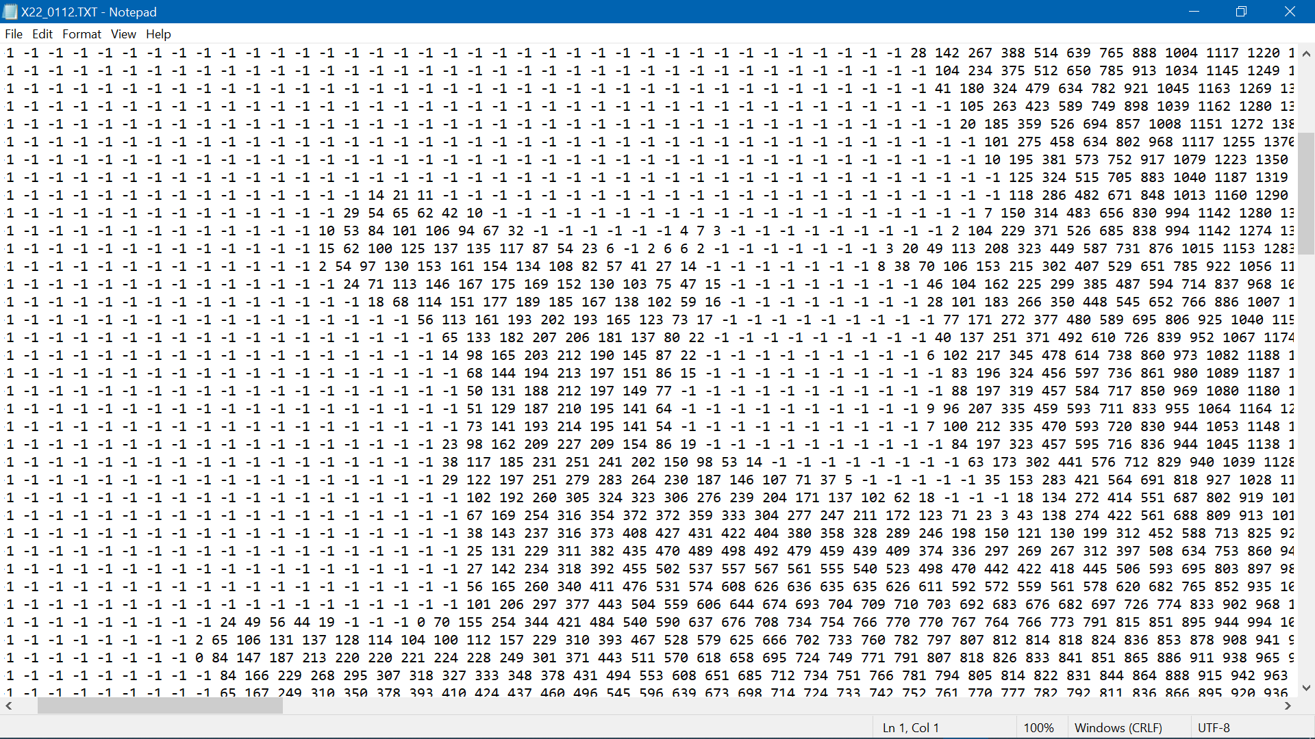
An example of a DEM text file
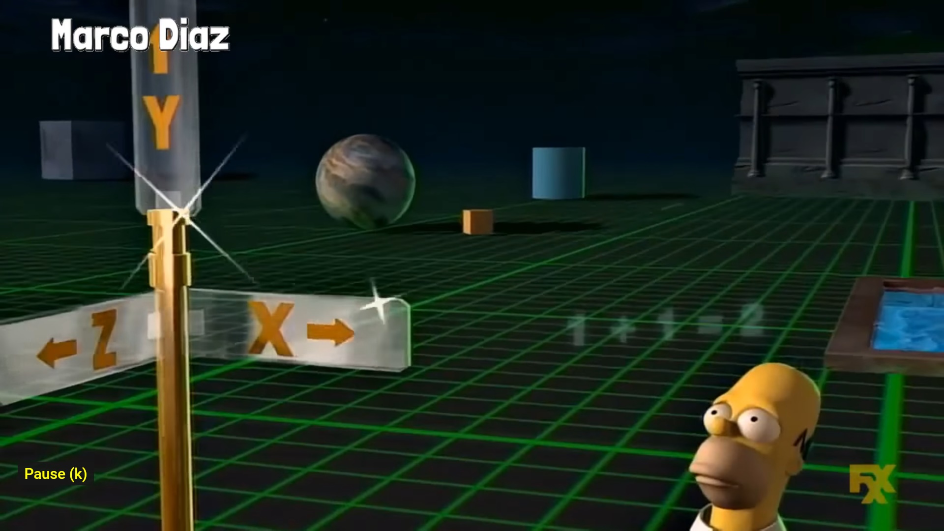
Courtesy of The Simpsons © 1995, made with identical technology although it was known as SGI (Silicon Graphics) at the time and the technology was known as CGI (Computer Generated Images) (fyi the Z points directly at you, initially)
So now you have everything you need for a render, all you have to do is connect a square of ZYX points as two triangles.
And a render of the same DEM drawn in triangles, emmisive materials using the Y value for Red and its inverse for Blue (for the most part, also I just spent six hours modifying and reverting my old program to get that shot 🧐)
Lighting & Materials


DEM drawn with Lighting and Materials though half the triangles are ommited, the green lines represent the vector of the (Vertex) Normals
A full rundown of Lighting and Materials is probably a bit beyond the scope of this website, though I will provide a general gist of it.
Normals are designated to every triangle or vertice of a triangle (depending on quality, latter known as Phong) and generally they are perpendicular to it, a light source or light sources are designated a point in space and the closer the angle that the light rays hit the normal to the opposite angle exiting towards the eye, the brighter, just like a mirror.
Whereas I may of come across as saying that the previously mentioned DEM was not really the biggest challenge in the world, to set it up with normals was a little perplexing.
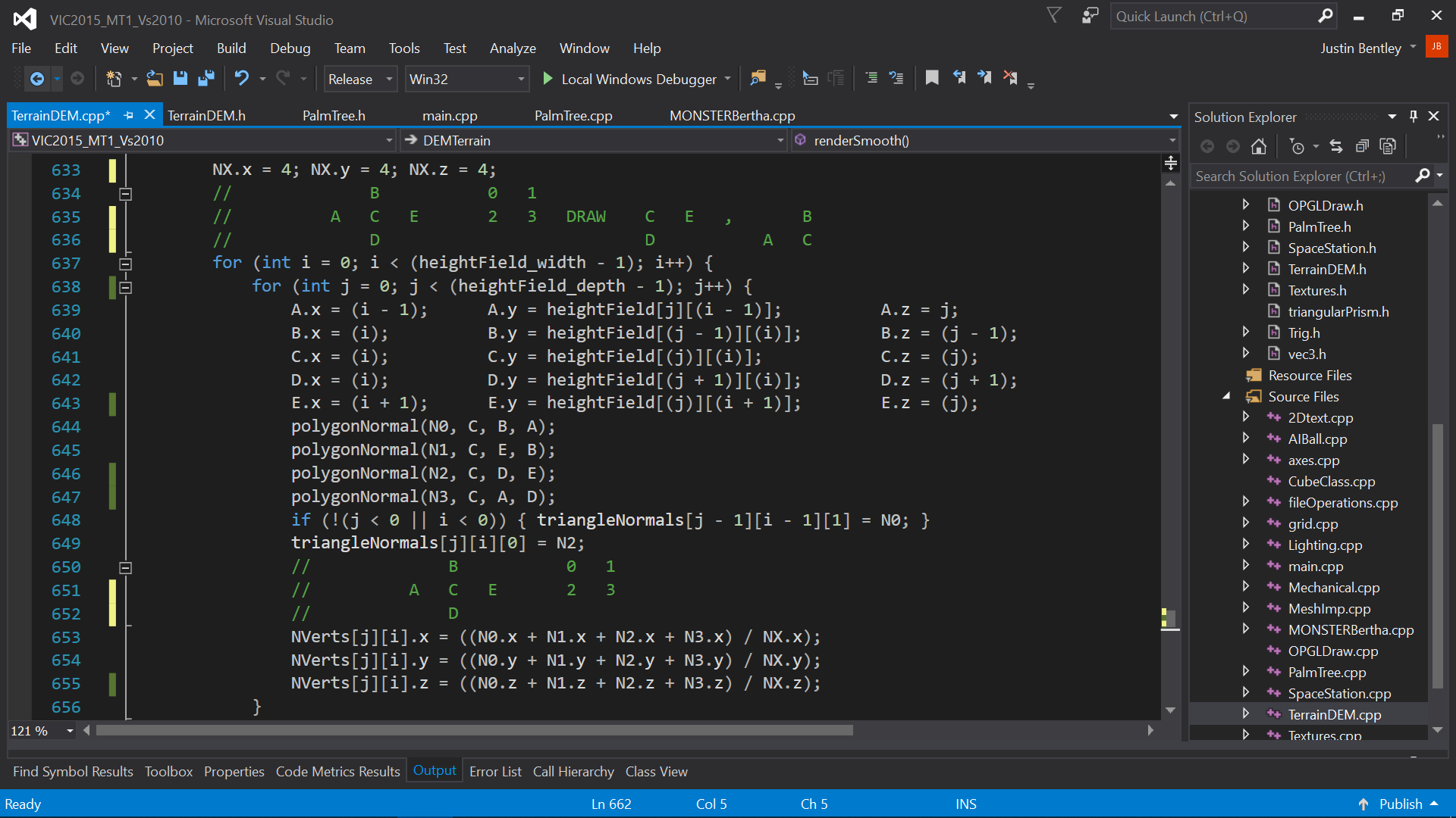
C++ code with a function to create normals for both vertice and triangle face normals.
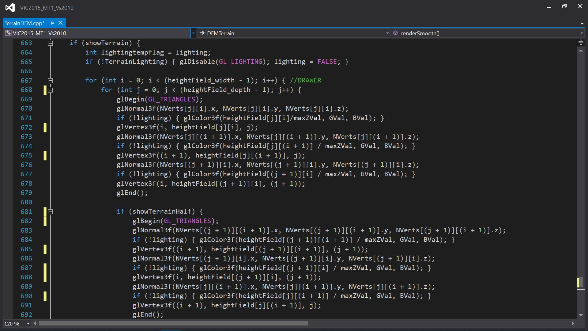
And for anyone interested the draw code (its not as hard as it looks 😉).
jump back
Final Assignment
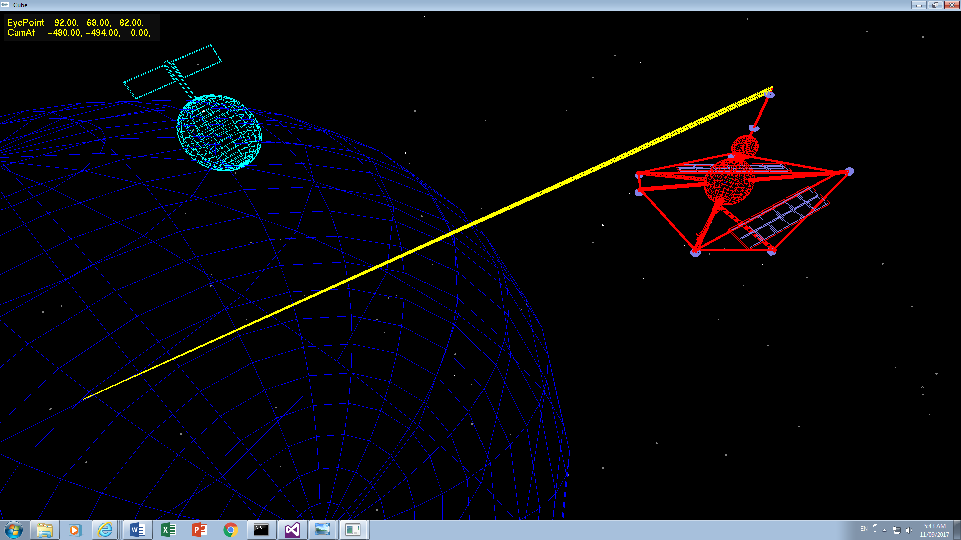
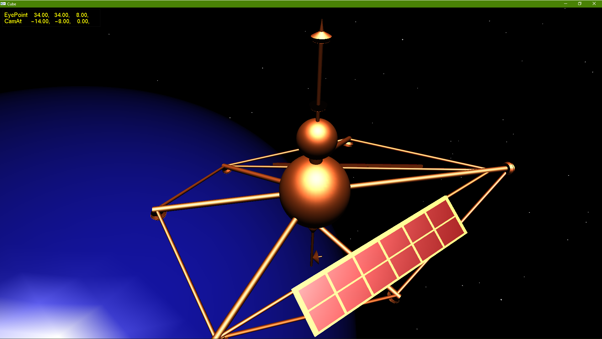
Put it all together, make it a Game, create a toon (character, also optional), add a Moon & blow up the MT1 Space Station!
Visual & Interactive Computing turned out to be my strongest unit during the Bachelor, perfect scores (some above) for all Assignments, a final score of 92/100 being a High Distinction, sure taught me how to Program (and C++) in bulk and though labourious to be honest I had a lot of fun.
jump back
Post Assignment
Holidays, Computer Aided Design & Palm Trees
Firstly, can anyone tell me what this is?
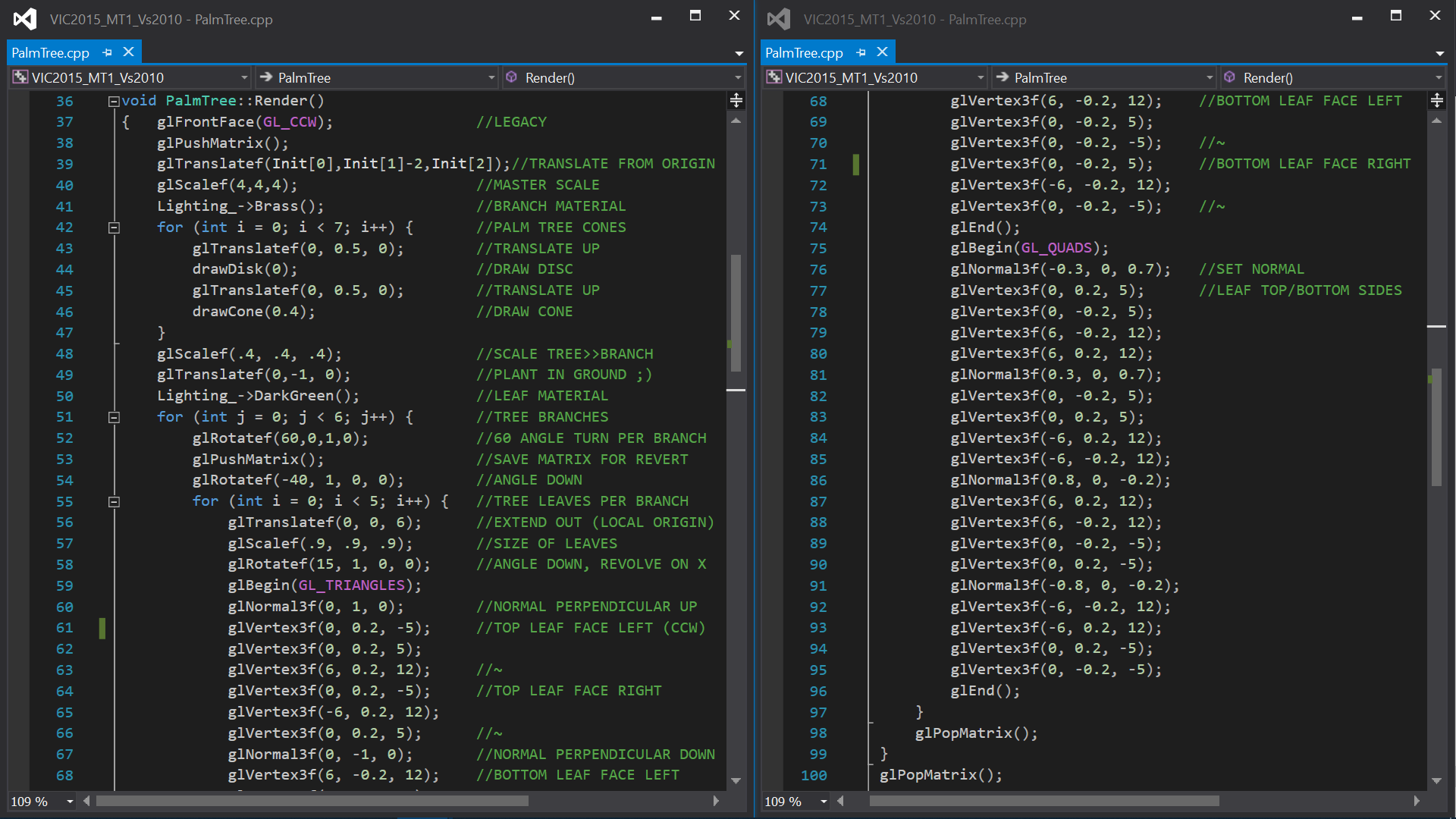

Thats Right its a Palm Tree!

Or alternatively, many of them!
Though the humble (and it was Lego inspired) Palm Tree turned out to be the last thing I ever made using the glTranslate etc method. Which was a shame ofcourse but we all knew that creating a object (or a Mesh as we would call it) using a CAD program was superior for many reasons. The number one most immediate reason for us was to relieve the CPU, after all, all those translates and scales are matrix mathematics and they add up fairly quickly.
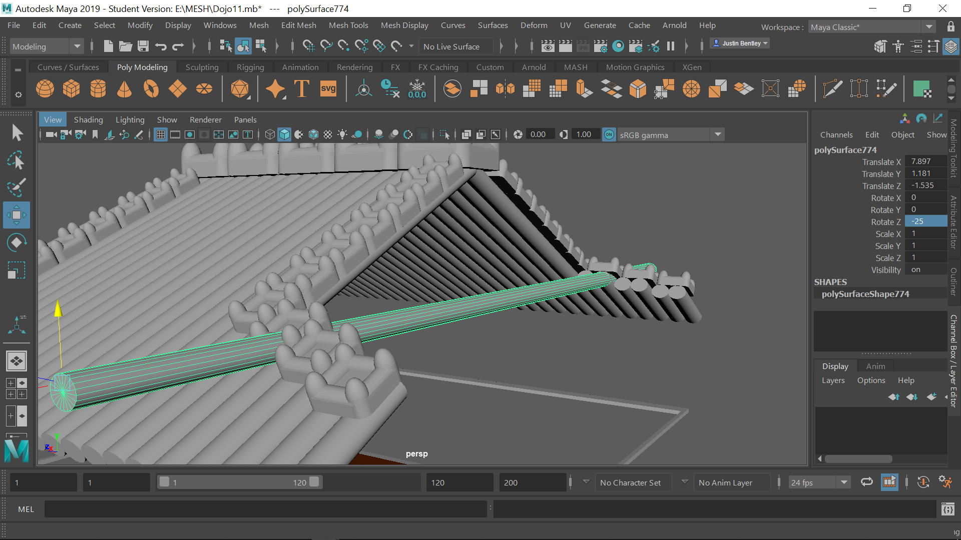
Although the other clear reason especially for something that is complicated is ease of use and Maya, its varients (or even simply Autodesk) or even a CAD program in general is undeniably easier and quicker and reasonably enjoyable to use
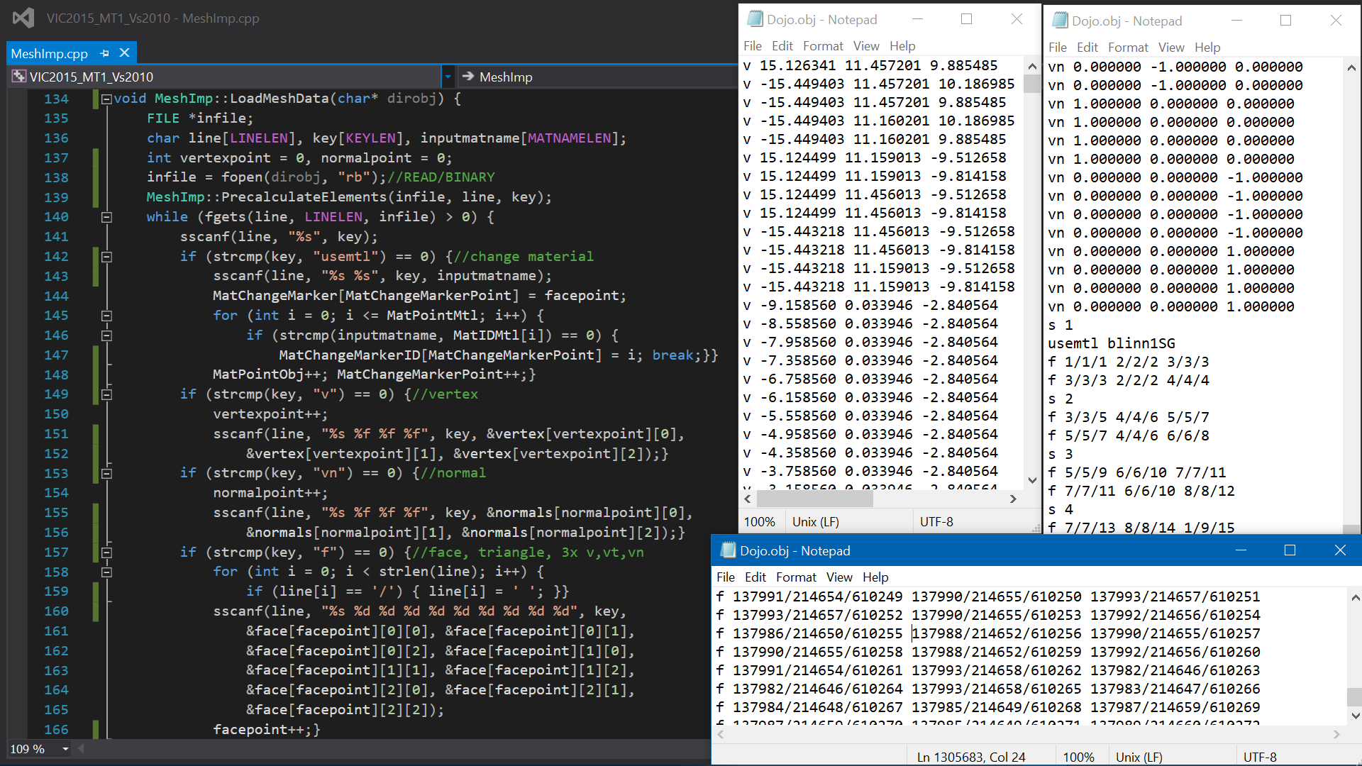
And ofcourse I wrote a importer to translate a Mesh .obj file into OpenGL (which I could probably write an entire webpage on alone) and luckily it was pretty much plug and play later on in ICTP, just with the addition of the 'vt' texture co-ords.

So, post assignment submission I wrote a mesh importer & created a Dojo/Training Room in Autodesk Maya in anticipation for ICTP although it turned out that this version of OpenGL was incompatible with the HTC Vive (which was already bought) so it was back to square one, a whole new version of OpenGL, a whole new game engine and a whole new story about that, in ICTP.